Hardware
On this page
SoC / board
- Allwinner A133 (
sun50iw10), SoC id0x1855. Marketed interchangeably as R818. USB descriptor in FEL reports board nameQUAD-CORE R818 EVB2, VID0x1F3A. - 2 GiB DDR4, ~8 GB eMMC (MMC 5.1), PMIC AXP806.
- Android board/product:
peony_evb2/peony-perf1,android.hardware = sun50iw10p1.
Thermal zones and what an app can read
Verified 2026-11-12 with read-only adb (shell user) on the reference panel, S1 Kiosk 0.4.3, kernel 4.9.170. The diagnostics pane uses these (#123).
| Path | Read |
|---|---|
/sys/class/thermal/thermal_zone0 |
type = cpu_thermal_zone, temp = 47999 (m°C), mode enabled |
/sys/class/thermal/thermal_zone1 |
gpu_thermal_zone, 47463 |
/sys/class/thermal/thermal_zone2 |
ddr_thermal_zone, 47463 |
a zone's temp |
-r--r--r-- root root, u:object_r:sysfs_thermal:s0 |
/proc/stat |
-r--r--r--, u:object_r:proc_stat:s0; SELinux is permissive, so the app can read it |
/proc/<pid>/smaps_rollup |
present (backported to 4.9); the shell user gets Permission denied for the app's pids |
Every app process, Gecko's included, runs as the app's uid (ps -A): the main process, and
:crashhelper_…, :gpu_… and :sandboxed_tab_…<n> from GeckoView. The main process's comm is
AndroidUI, not the package name.
FEL button
There is one unlabeled tactile button on the PCB (you must open the back cover to reach it). Hold it while applying USB-C power to enter FEL. The external case button and the Aqara pairing button do not enter FEL.
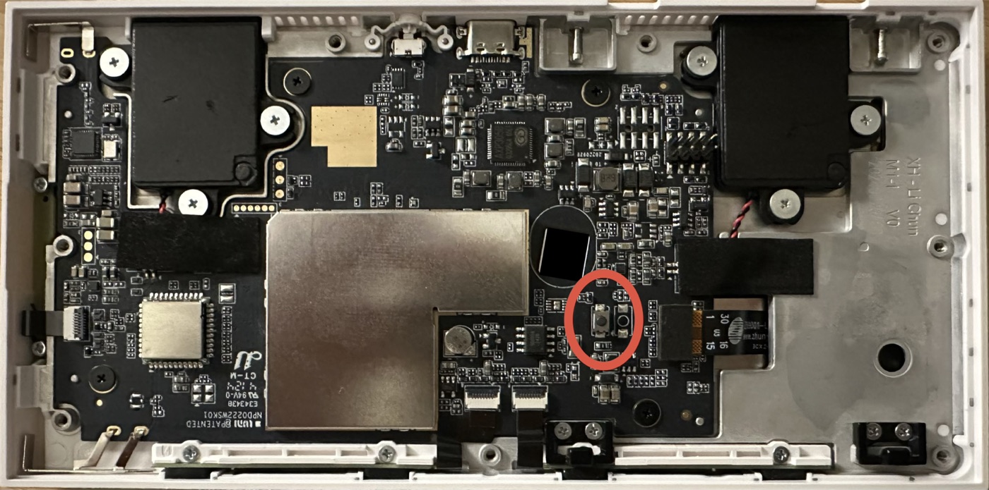
The FEL button (circled): a small tactile switch right of the shield can's notch, just below the round sensor window.
Debug UART console (3-pin header)
A 3-pin header exposes the serial console. The pads are flat (castellated/holes), so a firm or soldered connection is needed.
| Signal | Notes |
|---|---|
| GND | Find with a multimeter (continuity to USB-C shield / ground plane) |
| TX | Panel transmit — idles 3.3 V, streams boot log. Connect to your adapter's RX |
| RX | Panel receive — connect to your adapter's TX to type |
- Level: 3.3 V TTL. Do not use a 5 V adapter.
- Settings: 115200 baud, 8N1.
- There is also a separate 6-pin (2×3) connector — that one goes to the relay module, not the console. Ignore it.
The console gives a live root-capable Android shell (console:/ $), and catches U-Boot's Hit any key to stop autoboot.
Using an ESP32-S3 as the UART adapter (dev only)
End users won't need UART, but for development any ESP32-S3 works as a 3.3 V USB↔UART bridge — see tools/esp32-uart-bridge. It bridges the S3's native USB-Serial/JTAG (or a CP2102) to a hardware UART on two free GPIOs (default GPIO40 = TX → panel RX, GPIO41 = RX → panel TX), locked at 115200.
Wiring:
ESP32-S3 GND     -> panel GND
ESP32-S3 GPIO40  -> panel RX
ESP32-S3 GPIO41  -> panel TX
Verify the adapter before touching the panel by jumpering its TX↔RX and confirming a loopback echo.